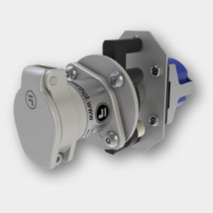
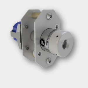
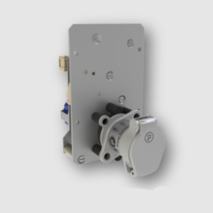
Khóa interlock LCU2-2-0-CLIS-V-A02022-H01CB. Sự kết hợp giữa khóa công tắc và bộ trao đổi khóa (key exchange). Có 2 tùy chọn dùng để lắp lên tủ điện có sẵn hoặc đã lắp sẵn hộp hoàn thiện.

Thông tin đặt hàng Khóa interlock LCU2-2-0-CLIS-V-A02022-H01CB2 FORTRESS
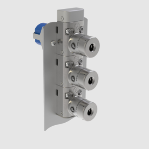
Khi vặn chìa khóa công tắc vào đúng vị trí. Các chìa khác có thể được rút ra và mang đi đến các vị trí cổng / cửa cần mở.Chỉ khi nào các chìa khóa khác quay về đủ thì mới có thể vặn chìa khóa công tắc trở lại vị trí ban đầu.
Sản phẩm này được thiết kế để sử dụng theo hướng dẫn cài đặt và vận hành kèm theo. Nó phải được cài đặt bởi nhân viên có năng lực và trình độ đã đọc và hiểu toàn bộ tài liệu này trước khi bắt đầu cài đặt. Bất kỳ sửa đổi hoặc sai lệch nào so với các hướng dẫn này đều làm mất hiệu lực của tất cả các bảo hành.Sản phẩm này không được sử dụng làm Bộ cách ly nguồn điện hoặc Dừng khẩn cấp. Thiết bị này là một thành phần được thêm vào hệ thống lắp đặt điện cố định đáp ứng các yêu cầu của tiêu chuẩn IEC/EN hiện hành. Tất cả các điện áp được sử dụng trên các thiết bị đầu cuối LCU / SCU đều phải cùng loại.
Standard Functionality
In the key exchange condition, keys are held captive in Normally in Lock(s) and can only be released on insertion and entrapment of the keys into the Normally Out Lock(s), which also operates the switch. Alternatively, where all locks are Normally In, the switch operated Normally In Lock must have the key released first, operating the switch, before the remaining can be freed (in order adjacent to the switch controlled lock).
| Technical Specifications | LCU / SCU | |
| Housing Materials | Mild steel with powder coat finish | |
| Lock Mechanism | Die-cast zinc body with stainless operating mechanism (selected separately) | |
| Minimum Operating Current | 5mA at 20v | |
| Safety Data | ||
| Standards | EN60947-3: 2009 ISO EN14119: 2013 EN13849-1: 2008 EN13849-2: 2012 EN62061: 2005 |
|
| Certifications | CE marked for all applicable directives | |
| Category | Cat. 4, PLe (EN/ISO 13849-1) and SIL3 (EN/IEC 62061) | |
| Functional safety data | B10d | 5,000,000 |
| DC | High 99% (with correct monitoring) | |
|
Maximum Permissible Wire Gauge |
|||||||||
|
Wire Type |
Units |
20A |
32A |
63A |
|||||
|
Single Core or Stranded |
mm² |
2 x 2.5 |
2 x 6 |
2 x 16 |
|||||
|
AWG |
2 x 12 |
2 x 8 |
2 x 6 |
||||||
|
Flexible Wire |
mm² |
2 x 2.5 |
2 x 4 |
2 x 10 |
|||||
|
AWG |
2 x 14 |
2 x 10 |
2 x 6 |
||||||
|
The 20A, 32A and 63A switches will accept 2 wires per terminal, one either side of the terminal screw. Only copper wires are to be used. |
|||||||||
|
Wire Strip Length |
|||||||||
|
The wire strip length is the length of wire left exposed at the end of a cable when the insulation is removed. The recommended lengths are shown below. |
|||||||||
|
Switch |
Strip Length (mm) |
||||||||
|
20A |
8 |
||||||||
|
32A |
11 |
||||||||
|
63A |
15 |
||||||||
|
Minimum Voltage and Current |
|||||||||
|
The standard 20A switch has been tested to work down to 5mA at 20V. For lower voltage and current requirements, please contact Fortress. |
|||||||||
|
DC Ratings |
|||||||||
|
The rotary switches are all AC but have the following DC ratings: |
|||||||||
|
DC Voltage |
20A Switch |
32A Switch |
63A Switch |
||||||
|
24V |
20A |
32A |
63 |
||||||
|
48V |
12A |
25A |
50 |
||||||
|
60V |
4.5A |
10 |
16 |
||||||
|
110V |
1A |
2 |
3 |
||||||
|
220V |
0.4 |
0.6 |
0.7 |
||||||
|
440V |
0.27A |
0.3 |
– |
||||||
|
Mechanical and Electrical Life |
|||||||||
|
The mechanical life of the lock and bolt mechanism is 1,000,000 operations. The life of the rotary switch is shown below: |
|||||||||
|
Switch Type |
Mechanical Life (N° of Operations) |
AC – 21A Electrical Life (N° of Operations) |
|||||||
|
20A |
1,500,000 |
100,000 |
|||||||
|
32A |
1,500,000 |
100,000 |
|||||||
|
63A |
1,500,000 |
100,000 |
|||||||
Tham khảo thêm tại: https://minhviet-jsc.com/hang-san-pham/giai-phap-an-toan-safety-solution